Product Detail
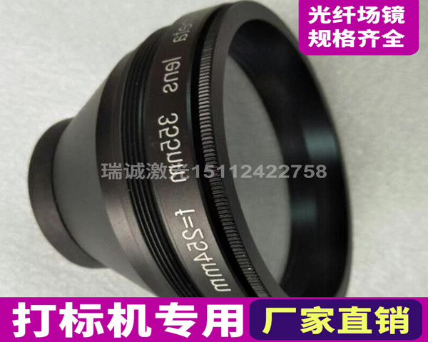
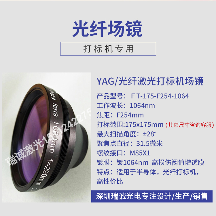
Laser Marking Galvo Lens
Related Products
- 532nm green light marking airport mirror
- 1064nm Fiber Marking Machine Special Field Mirror 110 * 110F160mm
- 1064nm scanning range 150 * 150F=210mm fiber field mirror
Custom Order
 15112422758
Call / Send specs for a quote
Custom to Drawing or Sample
Send us wavelength, size and coating specs — or a drawing or sample — and we will evaluate and issue a proposal. Prototype samples in 3-7 working days.
Scan to chat with us
Technical Specifications
| Model | 008 |
|---|
Basic definition of field lens:
A lens that works near the focal plane of the objective lens and can effectively reduce the size of the detector is called a field lens.
More precisely, the field lens should operate on the image plane of the objective lens. On the one hand, the object plane of the field mirror coincides with the main plane, and its magnification is 1 according to the characteristics of the main plane, so it does not contribute to the magnification of the system; On the other hand, the field lens should project the aperture surface of the objective lens onto the entrance pupil of the eyepiece. For a single lens, the aperture surface is also the exit pupil, which ensures that the exit light of the objective lens can pass through the eyepiece to the maximum extent possible. If used in a scanning system, the detector replaces the entrance pupil of the eyepiece.
Basic classification of field mirrors:
Classified by frequency band: 1064nm field mirror (also known as YAG field mirror), 10.6-micron field mirror (also known as CO2 field mirror), 532nm field mirror (also known as green field mirror), 355nm field mirror (also known as ultraviolet field mirror).
Classified by design concept: f-theta lens and telecentric lens. Telecentric lens has a high cost and is mainly suitable for f-theta lens in industrial systems.
reference material:
Laser scanning:
The main technical parameters of a field lens include: operating wavelength, entrance pupil, scanning range, and focused spot diameter.
Working wavelength: mainly depends on the wavelength of the laser, and the lenses of the field lens are coated at the given laser wavelength. If the field mirror is not used within the given wavelength range, it may be burned out by the laser or the required laser transmittance may be very low.
Incident pupil: also known as maximum incident spot. If a single mirror is used, the reflector is placed at the entrance pupil, and the maximum available beam diameter is equal to the diameter of the entrance pupil. The larger the entrance pupil, the smaller the diameter of the focused spot produced by the focusing mirror. Therefore, in situations where precise marking is required, we will consider using field mirrors with larger entrance pupils, such as fine marking and galvanometer welding.
Scanning range: The larger the range that the field lens can scan, the more popular it is among users. But if the scanning range is increased, the focused light spot will become larger and the distortion will also increase. In addition, the scanning range should be increased, and the focal length and working distance of the field lens should also be increased. The extension of working distance inevitably leads to the loss of laser energy. The diameter of the focused spot is directly proportional to the focal length, which means that as the scanning range increases, the diameter of the focused spot also increases. If the spot is not focused fine enough, the power density of the laser will decrease very quickly (the power density is inversely proportional to the square of the spot diameter), which is not conducive to processing. So users should choose the most suitable field lens according to different processing areas, or spare several field lenses with different scanning ranges. Focal length: It is related to the working distance to some extent, but not equal to the working distance.
Focusing spot diameter: For a scanning system with incident laser beam diameter D, field lens focal length F, and beam quality factor Q, the focusing spot diameter d=13.5QF/D (mm). So using a beam expander can result in a smaller focused spot
The main function of a field mirror is to:
(1) Improve the ability of edge beams to be incident on the detector;
(2) In the same main optical system, additional field mirrors will reduce the detector area. If the same detector area is used, the field of view can be expanded and the incident flux can be increased;
(3) It is possible to allocate the position of the image plane to place the modulation disk, in order to solve the problem of having nowhere to place the modulator;
(4) Make the non-uniform illumination on the photosensitive surface of the detector uniform;
(5) When using a flat field mirror, a flat field image plane can be obtained;
(6) In terms of aberration correction, it can compensate for the system's field curvature and distortion.