Detailed Explanation of Optical Component Plan
Today let's take a look at the optical component plan and how to understand the annotations on it for your reference.
The content of the optical component plan mainly includes the external dimensions, materials, technical requirements, and characteristics of the optical component.
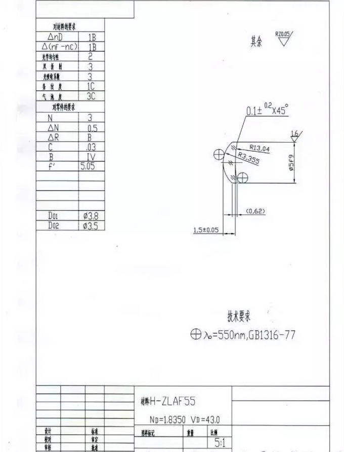
The main title bar contains the product name and code; Scale of the image; Material name, code, standard number; Design, change and other signature columns.
Requirements for materials:
Nd value (refractive index)
Light propagates at different speeds in different media. In physics, the refractive index is defined as n=1.2; v.1≤ v 2, The relative refractive index between the second medium and the first medium.
VD value (dispersion coefficient)
The same medium has different refractive indices for different wavelengths, which is the vd value of a substance=(nd-1)/(nf nc)
Optical uniformity
The consistency of refractive index at different points within the same transparent material.
Stress birefringence
When subjected to external forces (such as tight clamping) or internal forces (uneven cooling and heating), internal stresses will be generated inside the glass, breaking isotropy, and optical effects will cause birefringence.
Stripe degree
Stripes are areas of filamentous or layered chemical inhomogeneity in glass. The refractive index of stripes is different from that of the subject. The optical effect is equivalent to a thin cylindrical lens, causing stray light and affecting recognition accuracy.
Bubble degree
Bubbles in glass are caused by gas escaping during the melting and clarification process. The optical effect of bubbles is equivalent to the scattering and refraction caused by concave lenses.
Requirements for optical components
N-aperture number
△ R-Sample grade accuracy
C-lens eccentricity difference
B-Surface defects of optical components
D-Optical component center thickness
f′ -Lens focal length
Inverted dihedral angle - chamfer the edge of two intersecting planes
Circular optical components such as lenses should be labeled with the following parameters:
The curvature radius of the surface of the component;
Outer diameter and tolerance of the garden;
Center thickness and tolerance;
Chamfering dimensions and tolerances.
(In general, the edge thickness of a spherical mirror and the axial dimensions of the convex and concave edges of a meniscus lens are marked with reference dimensions.)
The following dimensional tolerances should be indicated on the drawings of prisms and other non-circular optical components:
Linear dimensions, angles, and tolerances of parts;
Chamfering dimensions and tolerances. The size of the illuminated surface area of the component.
If the chamfer of the edge is not drawn in the prismatic part drawing, the marked size is the same as the size of the sharp edge.
Annotation of chamfers
Generally speaking, chamfering is required to be specified in the graphics and text of optical component drawings. If the chamfer size on the surface is less than 2mm, the actual chamfer should generally not be pulled out. Only thin solid lines should be drawn at the chamfer and the size of the chamfer should be indicated. The chamfer line and chamfer line should be drawn with thin solid lines and marked with“ Sharp edge; (We usually use 'ls'); Inverted spine cannot be; mark )If all or part of the chamfer dimensions on the same drawing are the same, the technical requirements only need to indicate“ All chamfers *” Or“ Other chamfers *” And“ No chamfer *”.
Labeling of smoothness
The flatness requirements for each side should be indicated in accordance with relevant regulations. If the surface finish requirements are the same, only the upper right corner of the drawing is marked with 'ldquo; all*x”。 If the surface finish requirements are the same for most surfaces and different for a few surfaces, then only mark the machining code on a few surfaces, and mark other machining codes in the upper right corner of the graphic, such as“ The remaining X”.
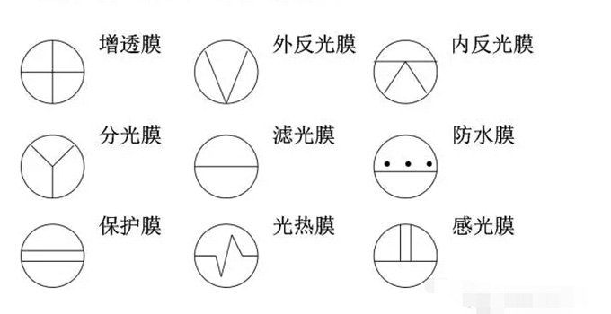
Coating characteristics
Special content of component drawings for flat mirrors, spherical reflectors, and spectrometers: The technical requirements describe the reflectivity, transmittance, and tolerances of the spectrogram film layer, and specify the quality standards for inspecting the film layer in the technical requirements.
The content of the optical component plan mainly includes the external dimensions, materials, technical requirements, and characteristics of the optical component.
The main title bar contains the product name and code; Scale of the image; Material name, code, standard number; Design, change and other signature columns.
Requirements for materials:
Nd value (refractive index)
Light propagates at different speeds in different media. In physics, the refractive index is defined as n=1.2; v.1≤ v 2, The relative refractive index between the second medium and the first medium.
VD value (dispersion coefficient)
The same medium has different refractive indices for different wavelengths, which is the vd value of a substance=(nd-1)/(nf nc)
Optical uniformity
The consistency of refractive index at different points within the same transparent material.
Stress birefringence
When subjected to external forces (such as tight clamping) or internal forces (uneven cooling and heating), internal stresses will be generated inside the glass, breaking isotropy, and optical effects will cause birefringence.
Stripe degree
Stripes are areas of filamentous or layered chemical inhomogeneity in glass. The refractive index of stripes is different from that of the subject. The optical effect is equivalent to a thin cylindrical lens, causing stray light and affecting recognition accuracy.
Bubble degree
Bubbles in glass are caused by gas escaping during the melting and clarification process. The optical effect of bubbles is equivalent to the scattering and refraction caused by concave lenses.
Requirements for optical components
N-aperture number
△ R-Sample grade accuracy
C-lens eccentricity difference
B-Surface defects of optical components
D-Optical component center thickness
f′ -Lens focal length
Inverted dihedral angle - chamfer the edge of two intersecting planes
Circular optical components such as lenses should be labeled with the following parameters:
The curvature radius of the surface of the component;
Outer diameter and tolerance of the garden;
Center thickness and tolerance;
Chamfering dimensions and tolerances.
(In general, the edge thickness of a spherical mirror and the axial dimensions of the convex and concave edges of a meniscus lens are marked with reference dimensions.)
The following dimensional tolerances should be indicated on the drawings of prisms and other non-circular optical components:
Linear dimensions, angles, and tolerances of parts;
Chamfering dimensions and tolerances. The size of the illuminated surface area of the component.
If the chamfer of the edge is not drawn in the prismatic part drawing, the marked size is the same as the size of the sharp edge.
Annotation of chamfers
Generally speaking, chamfering is required to be specified in the graphics and text of optical component drawings. If the chamfer size on the surface is less than 2mm, the actual chamfer should generally not be pulled out. Only thin solid lines should be drawn at the chamfer and the size of the chamfer should be indicated. The chamfer line and chamfer line should be drawn with thin solid lines and marked with“ Sharp edge; (We usually use 'ls'); Inverted spine cannot be; mark )If all or part of the chamfer dimensions on the same drawing are the same, the technical requirements only need to indicate“ All chamfers *” Or“ Other chamfers *” And“ No chamfer *”.
Labeling of smoothness
The flatness requirements for each side should be indicated in accordance with relevant regulations. If the surface finish requirements are the same, only the upper right corner of the drawing is marked with 'ldquo; all*x”。 If the surface finish requirements are the same for most surfaces and different for a few surfaces, then only mark the machining code on a few surfaces, and mark other machining codes in the upper right corner of the graphic, such as“ The remaining X”.
Coating characteristics
Special content of component drawings for flat mirrors, spherical reflectors, and spectrometers: The technical requirements describe the reflectivity, transmittance, and tolerances of the spectrogram film layer, and specify the quality standards for inspecting the film layer in the technical requirements.